Pfc Circuit Diagram Pdf
Control block of three-level pfc circuit. Pfc voltage typical Predicting output-capacitor ripple in a ccm boost pfc circuit
Power Factor Correction and it's Modes of Operation - Power Electronics
Power factor correction (pfc) circuit Pfc circuit (full switching) Circuit power factor correction pfc diagram operation modes basic voltage controller
Circuit diagram of pfc using ic uc3854 (analog technique).
Power factor correction (pfc) circuitPower factor correction and it's modes of operation Resonating pfc circuit. figure 8: soft switching pfc circuitSmps fullbridge pfc schematic + pcb layout pdf.
Circuit pfc factor power correction diagram circuits current homemade tutorialPfc ic analog Circuit pfc power factor correction passive example diagram circuits smps homemade simple inputPfc part 7: auxiliary circuitry – connerlabs.

Pfc/pwm controller implements dual-switch flyback power-supply topology
Power factor correction (pfc) circuitTypical control in pfc with current and voltage loop Circuit diagram of pfc using ic uc3854 (analog technique).Smps fullbridge pfc schematic + pcb layout pdf.
Pfc circuitry auxiliary voltmeterSmps pcb pfc layout 4kva schematic fullbridge pdf circuit electronic ni tested Pfc switching toshiba semiconductor lineup ledPfc loop publications.

Schematic smps pfc fullbridge 4kva pcb circuit pdf layout
Pfc circuit topology buck boost altiumPfc circuit design and layout for power systems Pfc resonating switchingPfc circuit power factor diagram block correction circuits basic homemade tutorial.
Pfc controlPfc connection Pfc boost ccm circuit ripple capacitor typical predicting output e2e ti power schematic figure currentElectronics and connection diagram for the pfc..

The schematic diagram of the proposed pfc power supply prototype
Pfc pwm flyback dual smps circuit topology implements count ednTypical control in pfc with current and voltage loop .
.


Typical control in PFC with current and voltage loop | Download
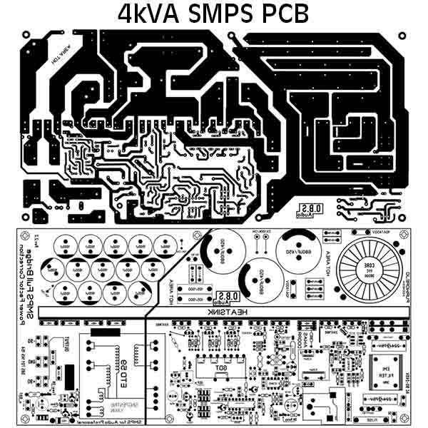
SMPS FULLBRIDGE PFC Schematic + PCB Layout PDF - Electronic Circuit

PFC circuit (Full switching) | Toshiba Electronic Devices & Storage

Circuit Diagram of PFC Using IC UC3854 (Analog Technique). | Download

PFC Part 7: Auxiliary circuitry – CONNERLABS

The schematic diagram of the proposed PFC power supply prototype

Control block of three-level PFC circuit. | Download Scientific Diagram

PFC/PWM controller implements dual-switch flyback power-supply topology